 Motorized Legs
Description
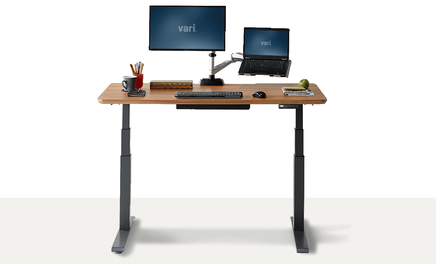
Electric motorized legs are used in standing desk to adjust the height of the desk as per the user need. The system is divided into three parts
- Motorized Legs
- Leg has a DC geared motor and encoder
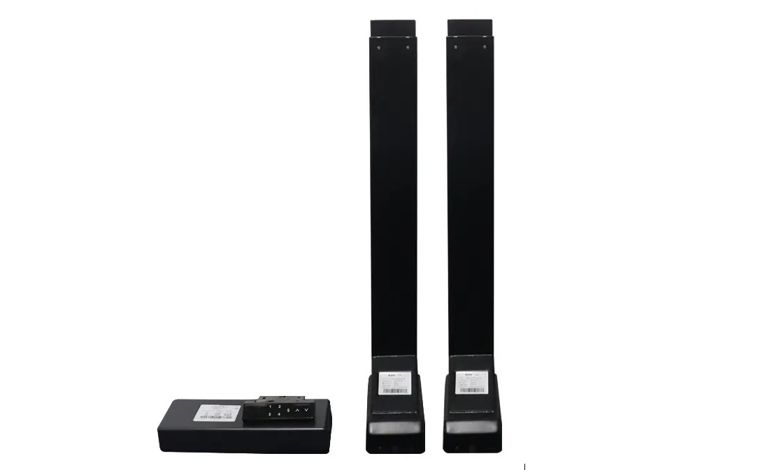
- Leg has a DC geared motor and encoder
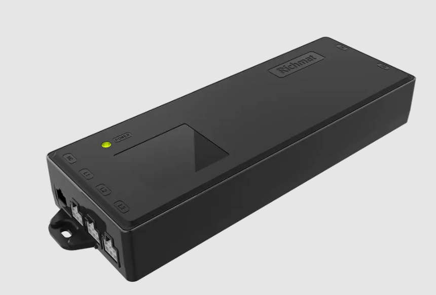
- Leg Controller
- Controller the drives the motor inside the legs
- It synchonize the legs movemnet
- It has protection circuit like overload.
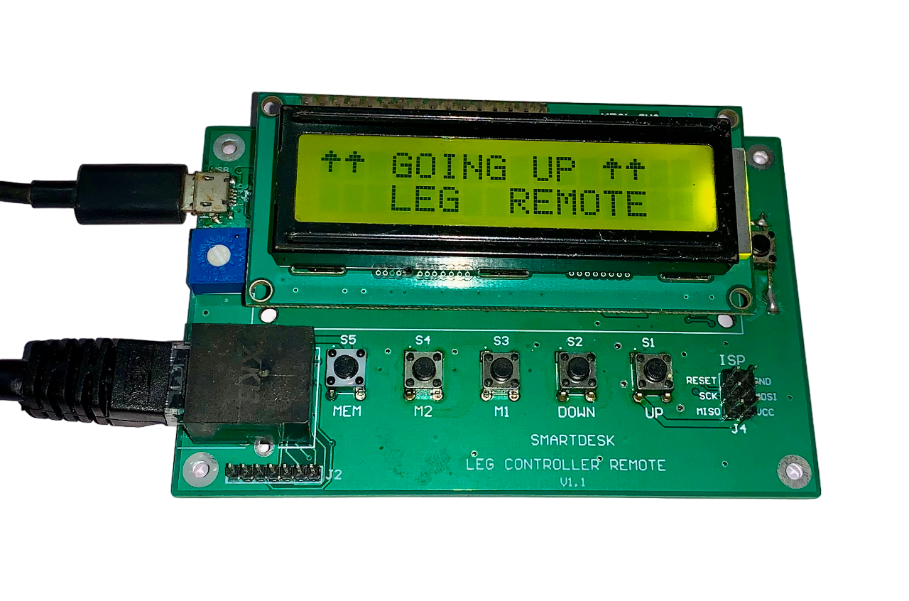
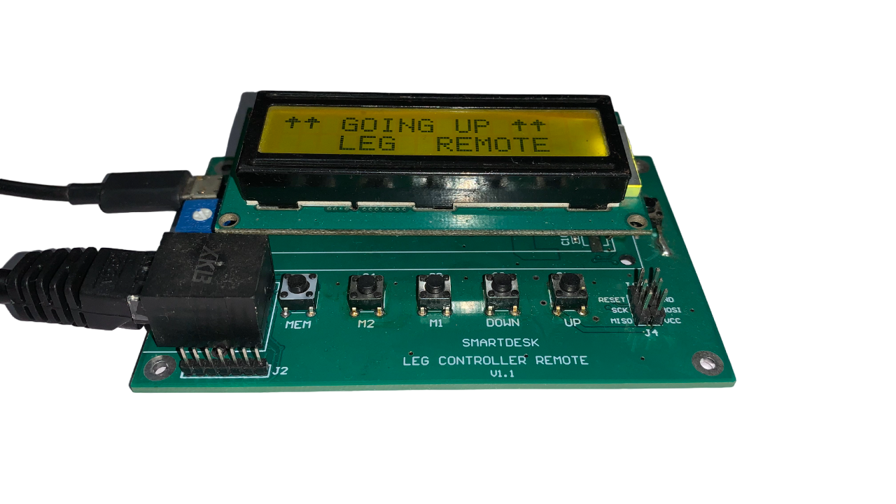
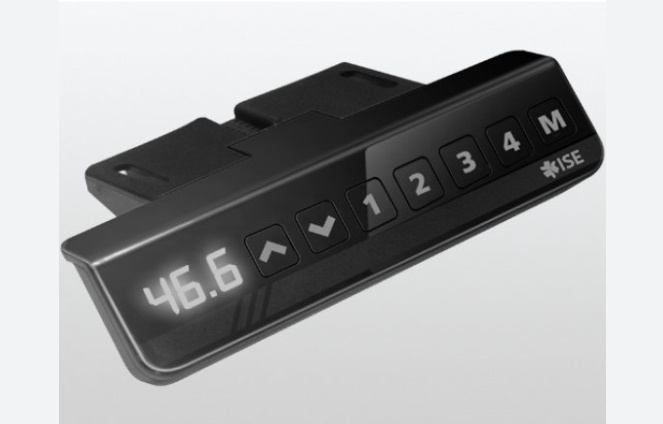
- Leg Controller Remote (Control Panel)
- Remote is used to control the up/down motion of leg
- Rempte display shows the current posiotn of legs
Objective
The objective of this project is to design a custom leg remote controller remote that will communicate with the leg controller. The system should be integrate with any product that uses the legs. For the example, It can be implemented in a system where the touchscreen display used or it can be used to control the leg motion from the PC (Using Software).
System
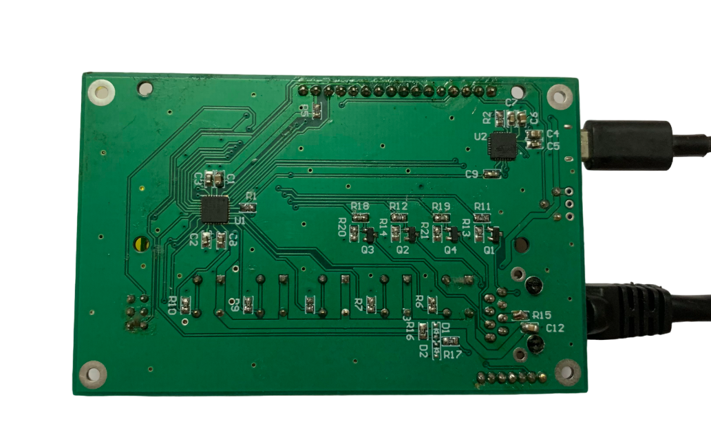
There is no documentation provided by the leg vendor and no information is available on the internet explaining the communication between the leg controller and remote. To checked the communication we have reverse engineered the remote control circuit and decoded the protocol and data used for communication. A protocol analyzer device is used to decode the data.
The remote controller send the data using UART protocol. The data is used to display the current position of the legs. Controller also send the error messages like overload, motor/cable fault.
The System uses the below components
- Atmega328p Controller
- 16x2 LCD Display
- CP2102 USB to TTL converter
The firmware is written in embedded C language.
The system mimics all the functions of the existing remote controller.
Remote Functions
- UP/Down: It is used to control the legs motion
- Memory: To store the current position of leg into the memory so that it can be used to move the legs into preset position
- Memory Location: The controller has 3 memory slots to store the position.
- The remote used to calibrate/reset the legs.
- Display the current positon and error messages
The system mimics all the functions of the existing remote controller.
Test Device Photo