Description
Reverse polarity protection circuit is used to protect electronic devices from damage that may occur due to accidental reverse connection of the power supply. Many products has a power supply input socket and there is big chance that the user can connect the power supply in reverse direction which can cause damage to the circuit. There are multiple ways to impliment the reverse polarity protcion circuit.
Reverse Polarity Protection using Diode
Using a Diode is the easiest and cheapest method for Reverse Polarity Protection but it has a problem of power leakage. When the input supply voltage is high, a small voltage drop may does not matter, especially when the current is low. But in case of low voltage operating system, even a small amount of voltage drop is unacceptable.
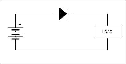
The voltage drop across a general purpose diode is 0.7V so we can limit this voltage drop by using Schottky diode because its voltage drop is around 0.3V to 0.4V and it can also withstand with high current loads.
At 3 Amps, power loss by a Schottky diode in the circuit will be:
3A x 0.4V = 1.2W
And for normal diode:
3A x 0.7V = 2.1W
As the current increase it cause more power loss and that power loss converts into heat. So use of diode in high current application is not suitable.
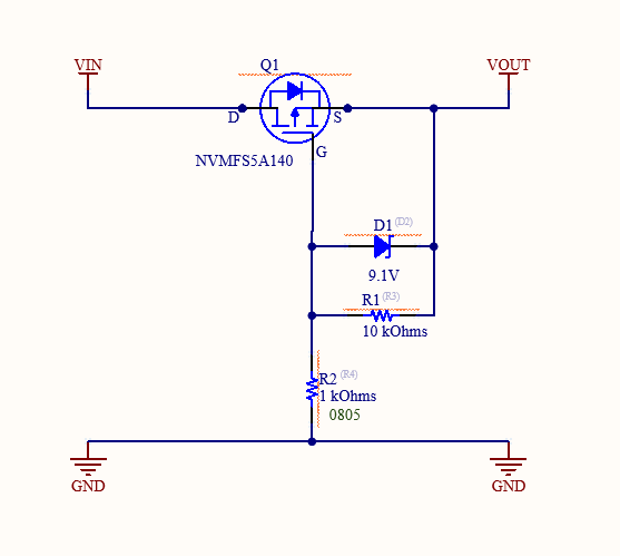
Reverse Polarity Protection using P-Channel MOSFET
Using a P-Channel MOSFET for Reverse Polarity Protection is more reliable than other methods, because of low voltage drop and high current capability. The circuit consists of a P-Channel MOSFET, Zener diode and a pull-down resistor. If the supply voltage is less than the Gate-to-Source voltage (Vgs) of P-channel MOSFET then we only need the MOSFET without diode or resistor. we just have to connect the gate terminal of the MOSFET to the ground.
Now, if the supply voltage is more than the Vgs then we have to drop the voltage between the gate terminal and source.
Working of Reverse Polarity Protection Circuit Using P-Channel MOSFET
When we connect the battery as per the circuit diagram, with correct polarity, it causes the transistor to turn ON and allows the current to flow through it. If the battery is connected backwards or in reverse polarity then the transistor turns OFF and your circuit gets protected.
This protection circuit is more efficient than others. when the battery is connected in right way, the P-Channel MOSFET will turn ON because the voltage between gate and source is negative. Formula for finding the voltage between gate and source is:
Vgs = (Vg - Vs)
When the battery is connected incorrectly, the voltage at gate terminal will be positive and we know that P-Channel MOSFET only turns on when the voltage at gate terminal is negative (minimum -2.0V for this MOSFET or less). So whenever battery is connected in reverse direction the circuit will be protected by the MOSFET.
Now, let’s talk about the power loss in the circuit, when the transistor is ON the resistance between drain and source is almost negligible but to be more accurate you can go through the datasheet of the P-Channel MOSFET. For NVMFS5A140 P-channel MOSFET the Static Drain-Source On-Resistance (RDS(ON)) is 0.0042Ω(max.). So, we can calculate the power loss in circuit like below:
Power Loss = I^2R
Let’s assume the current flow through the transistor is 1A. So the power loss will be
Power Loss = I2R = (1A)2*0.0042Ω = 0.0042W
as compare to the diode’s power loss this power loss is very less. That’s why using a P-Channel MOSFET for Reverse Polarity Protection is far better than other methods. It is little bit costlier than diode but it makes the protection circuit much safer and efficient.
We have also used a Zener Diode and a resistor in the circuit for the protection against exceeding gate to source voltage. By adding the resistor and the Zener diode of 9.1V, we can clamp the gate-source voltage to a maximum of negative 9.1V, hence the transistor remains safe.
You can select the PMOS as per the your requirement. Check the below parameter while selection
- Rds (Drain to Source resistance)
- Vgs (Gate voltage should not increase above this limit in reverse polarity condition)
- Id (Max current)
- Vdss (Max reverse polarity voltage)
- Mosfet Package